|
PCV GAS CONDENSER |
|
Background Information: |
|
Q: What is PCV? |
|
PCV: Airing Out the Crankcase |
|
PCV stands for Positive Crankcase Ventilation and was introduced to automobiles in 1961 (CA) and 1963 (entire USA). This was the first in a continuing series of emission control systems designed to help reduce auto pollution. PCV has helped to reduce up to 20% of an engines emissions while keeping the internal workings of the engine cleaner. It uses the vacuum of the engine to draw crankcase vapor back into the manifold and reroute them back through the engine. These crankcase vapors are the blow-by gases that escape past the rings and find their way into the crankcase during normal engine operation. They contain raw fuel, water vapor, oil fumes, and exhaust gases. The system basically allows the gases that normally slip through the gaps in the rings to be recycled through the engine, rather than left to puff out into the air. (however if your rings are worn much larger amounts of gases slip past and cause an excess of pressure which can blow oil out of a oil breather, and if your vehicles breather happens to go into your air cleaner it can slowly soak your air cleaner with oil)
The basic system has a valve, called a PCV valve. This valve allows gas from the crankcase to flow out but not let any gas flow in the other direction. This is done so that a backfire cannot travel back into the crankcase and ignite the crankcase vapors. This valve usually is placed on the valve cover and a hose goes from it to a vacuum port on the carburetor that goes into the manifold. Then there is an open type oil breather on the oil cover. This is how my engine is set up. Not very complicated but it works.
A slightly more complicated system has a hose that goes into the air cleaner for a breather. This way if there is more gases than the PVC valve can handle they are also recirculated through the engine instead of escaping into the atmosphere. This is known as a closed system.
That is the basics of the PCV system. But in those basics is the inherent problem. Most of the gases drawn back into the engine are not real favorable, and are not real clean. A small portion of these gases will slip past the rings and find its way back through this cycle. Eventually you get a lot of water, hydrocarbons and other exhaust constituants that build up in the engine. To solve this problem I built and installed a PCV Jar. The following information was originally available on the KeelyNet BBS and is currently on-line at various KeelyNet mirror sites as well as the KeelyNet site.
|
|
|
|
KeelyNet Website.
Bill Beaty's mirror site of Original KeelyNet files.
Electromagnum KeelyNet mirror site.
|
|
|
|
|
|
PCV Jar |
|
Taken from KeelyNet BBS (214) 324-3501, Sponsored by Vangard Sciences,
PO BOX 1031, Mesquite, TX 75150 |
|
There are ABSOLUTELY NO RESTRICTIONS on duplicating, publishing
or distributing the files on KeelyNet except where noted! |
|
March 28, 1992. |
|
Here is a device that you can build that will improve your gas mileage by at least 25%, and also keep
your oil, engine and spark plugs cleaner, thus allowing your engine to have a much longer life. The device can be made for a total cost of
about $12.00, and about two hours of labor. |
|
|
|
The device consists of a 1 quart jar, a small V8 fruit juice can or similar container, window screen, BBs',
hoses, washers and clamps. The device is installed in between the PCV valve of your automobile engine and the vacuum source the PCV
valve is normally connected to. The device condenses the oily vapors normally sucked into the combustion chamber as part of the pollution control systems, in a container of BBs', where the vapors condense around the BBs', and drain into the bottom of the jar. If you can find
them, use glass beads the same size of the BBs'. I have been unable to find any, but I know that they are made. |
|
|
|
Blow by gases, containing gasoline vapors, are drawn back into the engine for burning. Combustion efficiency
is improved as a result of the oily vapors collected in the jar, rather than contaminating the fuel/air charge in the combustion chamber. |
|
|
|
Obtain a 1 quart jar, preferably with a wide mouth. The wide mouth is necessary for the juice can containing the BBs' to fit in the jar. Being careful not to damage the sealing gasket of the jar lid, locate and cut a 1/2 inch hole in the very center of the jar lid. |
|
|
|
Locate and cut another 1/2 inch hole midway between the hole in the center of the lid and the outside edge of the jar lid. At this point, the jar lid has two, 1/2 inch holes cut in it.Try to keep the holes neat without any excess metal protruding above or below the lid surface. |
|
|
|
Obtain a length of 1/2 inch, all threaded pipe, and 6, 1/2" nuts. I use the pipe and nuts, that are used in lamps and lighting fixtures, and buy it at lamp shops. Some of this pipe has a seam in it, which you don't want. This device must be air tight, as engine vacuum
is connected. Cut 1, 2-1/2 inch length and 1, 1-1/2 length. |
|
|
|
Cut the end with the pouring hole, out of the small V8 juice can. Wash out and dry the can. Cut a 1/2 inch hole in the center of the juice can. Using 1/2 inch nuts, and fender washers and silicone gasket sealer (you'll have to enlarge the holes in the washers to fit the 1/2 inch pipe), install the 2-1/2 inch length of pipe in the V8 juice can. |
|
|
|
Leave about two threads of the pipe, showing down inside the can. Use the fender washers on both side of the juice can to provide support. This can will be eventually filled with BB's, and the washers are necessary because of the weight. |
|
|
|
Take the 1-1/2 inch length of threaded pipe, 2 nuts and some silicone gasket sealer, and install in the hole of the jar lid, NOT the hole in the very center. Leave 2 or 3 threads of the pipe showing on the underside of the jar lid. |
|
|
|
Back to the juice can. Cut a piece of aluminum window screen to neatly fit the inside of the juice can, and push it down into the juice can, leaving no gaps for the BBs' to roll into the threaded pipe. Fill the can completely, with copper plated BBs'. |
|
|
|
Take another piece of aluminum window screen, and pull it over the end of the juice can, leaving about a 1/2 inch skirt of screen. Using a large worm gear type hose clamp, gently tighten the clamp, snugging the screen to the outside surface of the juice can.
You have to be careful here. You want to tighten the clamp just enough where the juice can STARTS to deform. |
|
|
|
Install this can full of BBs' in the center hole of the jar lid, using washers and nuts. Leave about 1/2 inch of space between the top of the juice can and the other pipe installed in the jar lid, to allow the blow-by gasses to exit the jar. |
|
|
|
Install 1/2 inch elbow on both pipes protruding from the top of the jar lid. Install a 1-1/2 inch piece of pipe into each elbow. |
|
|
|
Obtain 1/2 automobile heater hose, and connect the jar to the engine as follows: |
|
|
|
* From the center pipe of the jar lid, connect to the PCV valve. If the hose is too large, use a worm gear clamp to secure the hose. |
|
|
|
* From the other pipe in the jar lid, connect a 1/2 inch section of heater hose to the vacuum source of the engine. |
|
|
|
MAKE SURE THAT THE JAR IS ABSOLUTELY AIR TIGHT ! ! If not, you will know what is meant by a vacuum leak. |
|
|
|
Now for the hardest part: You want to locate a spot in the engine compartment to mount a 1 pound coffee can, in
which to hold the jar. Try to locate a place where the hoses can be kept as short as possible. |
|
|
|
Cut several holes in the bottom of the coffee can to let any water drain out that may get in the can after a hard rain or that you have driven through. Cut a couple of pieces of the hose to wedge between the coffee can and the jar, to keep it snug and not bouncing
around. |
|
|
|
To make this assembly blend into the engine compartment, paint the jar lid, juice can and the coffee can, flat black. Consider using hoses the same color as the other engine compartment hoses. |
|
|
|
Depending on how far you drive, the jar will probably require emptying about once a month. Vehicles which are driven short distances and the engine never really gets up to maximum temperature, will require that the jar be emptied about once a week. |
|
|
|
The jar will contain mostly water, as a result of condensation that takes place in the oil pan. The liquid in the jar contains unburned hydrocarbons, water and sludge. The liquid is also mildly acidic, as a result of the water vapor and the unburned hydrocarbons, combining. Some people have noticed a slight burning sensation, if the liquid gets on the skin. |
|
|
|
About every 30,000 miles or so, wash out the BBs' with varsol to keep the passage ways open. Your engine will stay cleaner and last much longer. Some people have claimed they have gone 500,000 miles without a rebuild. Three hundred thousand mile claims are common. The most mileage increase heard, has been 40%. Twenty five percent is much more common. |
|
|
|
You will not believe the sludge and "gunk" that builds up in the jar. I broke an oil pump shaft in an engine with 185,000 miles on it, and when the oil pan was pulled, there wasn't any sludge or buildup. I installed the jar when the engine had about 72,000 miles on it. Additionally, the emission test readings are much lower. |
|
|
|
This is one project where you'll get a return on your money and efforts, very quickly. |
|
Jerry W. Decker.........Ron Barker...........Chuck Henderson |
|
Vangard Sciences/KeelyNet |
|
|
|
|
|
My PCV "Jars" |
|
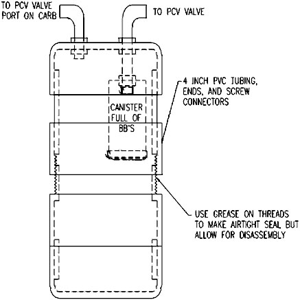
When I built this I didn't like the idea of a glass jar, especially since my truck rides like a truck. On my original unit, I used 4 inch PVC pipe. It was two end caps with a large screw fitting in the middle so I could take it apart and clean it out easily. I spread grease over the threads before I screwed it together to seal it. The guts of it were as was described in the KeelyNet file above. Then I used large hose clamps to attach the PVC canister to brackets made out of flat steel stock. This way nothing is mounted permanently and it is relatively simple to take apart and put back together. Here is a drawing of what my canister looked like.
|
|
|
|
|
|
|
|
It worked, sort of and only for a while. All it was doing was collecting anything that made its way through the PCV valve and kept it in the tank. I noticed no milage or power gains. Eventually the vibration of driving caused the can to come apart and the whole thing fell to the bottom of the PVC canister. But what it did catch was quite amazing and it was stuff that you definitely would not want to be feeding back into the engine. I set out to make a much better unit that was much more serviceable as well as easy to experiment with. |
|
|
|
The first step if you are going to build one of these is to look at the valve covers you have on your vehicle. Look where the PCV valve goes in and see what is behind it. I originally had a set of high rise Holley valve covers designed for race cars. These had no baffling behind the PCV or breather holes. Any oil that happened to be slung up by the rocker arms when there was enough crankcase pressure was pushed through. I noticed that in the course of about 2000 miles at least a quart of oil would be pushed into my canister. Now I knew why whenever I checked the oil, it was always low. I then purchased a set of GM aftermarket chrome valve covers. These had baffles behind both the PCV valve hole and the breather hole. They make filling the engine with oil a pain, but the collected oil is now under 1/4 of a quart in 2000 miles and most of what is collected is far more sludge and water than oil. I would assume most stock valve covers made in the last 10 to 15 years have these baffles on them, if not you should buy a set before you build one of these. Other idea may be to make some type of a plate in a V shape that would bolt on. kind of a splash guard that keeps oil on the rocker side of it and away form the valve cover side of it. I know I saw one advertized in a magazine once. It was supposed to help keep the rocker arm assemblies oiled better. It would also serve the purpose of keeping the oil in the engine rather than being pushed out the PVC valve or crankcase breather. |
|
|
|
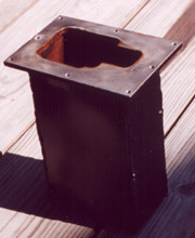
In my new design I wanted to make something that was much easier to service, much stronger than PVC and something that led to easier changes, especially in the small "can" inside. I decided to make a metal canister. This was constructed out of 16 gage steel. It was about 4 inches wide, 6 inched deep and about 10 inches tall. The top was made of 1/4 inch thick steel that had a large hole milled into it. Around the edge of the 1/4 inch top plate are nine 1/4-20NC tapped holes to affix the cover onto it. The whole cansiter was air-tight except for the large hole, the tapped holes are outside of the canister. Here is a picture showing the finished canister. |
|
 |
|
|
|
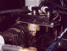
The cover for this canister was the same size as the cover welded on the canister. It had nine clearance holes for 1/4-20NC bolts that were in the same location as the 1/4-20NC tapped holes on the canister. This lid has the mounting bracket welded to it which, in my case, was a piece of one inch angle iron that bolts to the same bracket as the air conditioner compressor. This lid also has two pipes that go through it and are welded for an airtight seal. The first is a 2-1/2 inch long piece of standard 3/4 inch diameter pipe, threaded on both ends. This is the pipe used for the hose going to the PCV port on my carburetor. The second is a four inch long piece of 3/4 inch diameter pipe threaded on both ends. This is where the hose coming from the PVC valve connects to. The other end is covered by a screen mesh (same as used for screen windows) held in place with a hose clamp. (I put this on a lathe and machined a small groove wide enough for the clamp to fit in, about 0.02 to 0.03 inch deep. Just enough to keep the clamp from slipping either way on the pipe). Above this, welded to the pipe and lid, is an end cap for two inch diameter pipe. A hole for the 3/4 pipe is bored in the center of the end. This is the cover for my "can" and the threaded cap allows for the "can" to screw on and off easily. The screen is to keep any contents of the can from finding their way up the hose toward the PCV valve should I hit a rather large bump or something. Here is a picture of the installed lid with both pipes and end cap welded on. |
|
 |
|
|
|
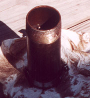
For the "can" I used a 6 inch long piece of 2 inch diameter pipe threaded on one end. This threaded end screws into the end cap welded on the lid. On the other end a groove is machined (again on a lathe) about the width of a hose clamp and 0.02 to 0.03 inches deep. This is for the hose clamp that holds the screen onto this end. This "can" can now be filled with various catalysts to help break down the oil and sludge that enters the canister. Here is a picture of the lid with the catalyst can attached and the can itself with stuff in it. |
|
 . . . . . . . . |
|
|
|
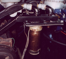
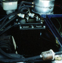
To assemble this in the vehicle a gasket made from normal gasket material from the autoparts store, seals the lid to the canister. Elbows are threaded onto the two pipes with brass hose barbs threaded into these. The PCV hose is cut and run into and out from this. My canister warped some when I welded it up and so it now one of the sides pops in a bit when engine vacuum is applied to it. Nothing to worry about since it would take much much more vacuum than this to collapse it but this lets me know it is holding a good vacuum and not leaking. Eveytime I shut off the engine it pops back out. So hearing this sound is a good thing for me. (I also have a vacuum guage in my dash just to verify I have no vacuum leaks). Here is a picture of the installed unit. |
|
 |
|
|
|
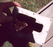
Upon running with the unit I initially found a lot of junk accumulate after the first few months (it was summer time) After a while not as much accumulated. However once it turned to winter, I checked it after a few months in the cold, The unit was nearly half full of sludge and a lot of water. This is from condensation due to the cold and hot experienced by the engine in the winter. I had probably close to a quart of water taken out, and kept out of my engine. This unit is a must to keep an engine water free. I suggest that if you are going to play with water injection or a water bubbler, you have one of these to keep the water out of the crankcase, because this is not where you want water to build up. Here is a picture of the unit with a bit of oil and sludge from one time when I emptied it. |
|
 |
|
|
|
What to run for a catalyst? |
|
|
|
Discussion with a few people who have worked with this type of a unit has given many ideas on what to fill the can with. The idea with the can is to put in materials that would break down the oil and sludge into lighter hydrocarbons. These would evaporate and be sucked back into the engine to be burned with the normal fuel and air. Left behind would be the partially burned hydrocarbons and heavy varnishes and oils that do not burn well anyway. Discussion with Bruce McBurney has yielded the following list of items to try in the can: Copper, Zinc coated BB's, Iron chunks, Silica Gel, Brass chunks, Aluminum chunks and adding a ring magnet over the tube with the south pole facing the BB's. The idea is to find which of these acts as a catalyst to the oil and crankcase gasses. The glass beads mentioned in the KeelyNet file were most likely the silica gel, since this actually disassociates water into hydrogen and oxygen (I was told this somewhere but have not been able to confirm it) so this would be useful in breaking down any water entering. One could also try adding in the contents of a catalytic converter, since these are designed for this exact purpose only with exhaust gases. The type of motor oil also will affect the working of this unit. A lot of oil now days is made to withstand much hotter running for longer so it is much more difficult to break down. One suggestion is to run a cheaper oil and change it a bit more often. This way it will be much easier to break down anything in the unit. I run Castrol in my truck and cannot say I have seen it being broken down to any great extent in the unit. This is probably not the best oil for use with this unit if breaking down of the contents is one of the major goals. One this is certian though, the unit does catch a lot of stuff. Black, gummy, acidic stuff that you don't want back in the intake manifold. This unit helps keep this stuff out of the engine and out of the air, making the engine last longer and the air easier to breath. I find it has been well worth the few hours I spent building it. Please send me any feedback you have on this so I can update this page. Thanks! |
|
|
|
|
|
Back to main page.
Back to Projects Page.
E-mail me at herningg@hotmail.com
|
|
|
|
This Page was last updated on 9 January 2001.
|
|
This page created and maintained by Garrett Robert Herning.
|